Arcturus (α Boo)
Arcturus is a digital pinhole camera built around the combination of a USB HD webcam and a Raspberry Pi Zero, housed in a ladies’ powder compact and powered by a USB lithium-ion power bank.
- Motivation
- Design
- Gallery
Design
The Parts
There are three main physical components that come together to create the pinhole camera, a Raspberry Pi Zero, a USB webcam and a ladies’ powder compact. I had got my Pi free on the cover of the MagPi magazine last year, but you can buy them for £4 / $6 assuming they’re finally back in stock! There’s no need to get the “Essentials Kit” unless you want it for other reasons. The only extras needed are a microSD card, a micro USB to USB adapter and optionally a mini DVI adapter if you want to connect to a TV to see it booting.
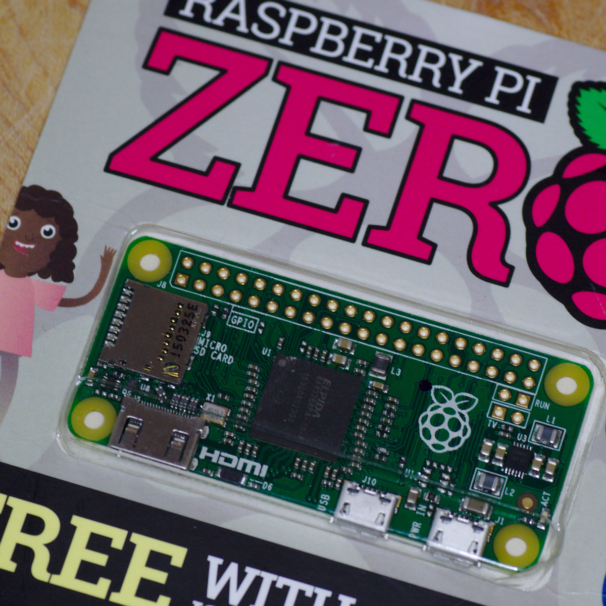
Raspberry Pi Zero, free with MagPi Magazine, to be used to control the webcam, capturing images to an SD card
More or less any USB webcam should do the job, but the more compact the circuit board the better. I got a Hercules DualPix HD webcam on eBay for a mere £0.99 and was pleased to find its internal circuit board was tiny. It is hard to tell what size the board will be from looking at the case. Given the price they’re available for on auction sites, its worth just taking pot luck and if it doesn’t work out, just try and find a second.
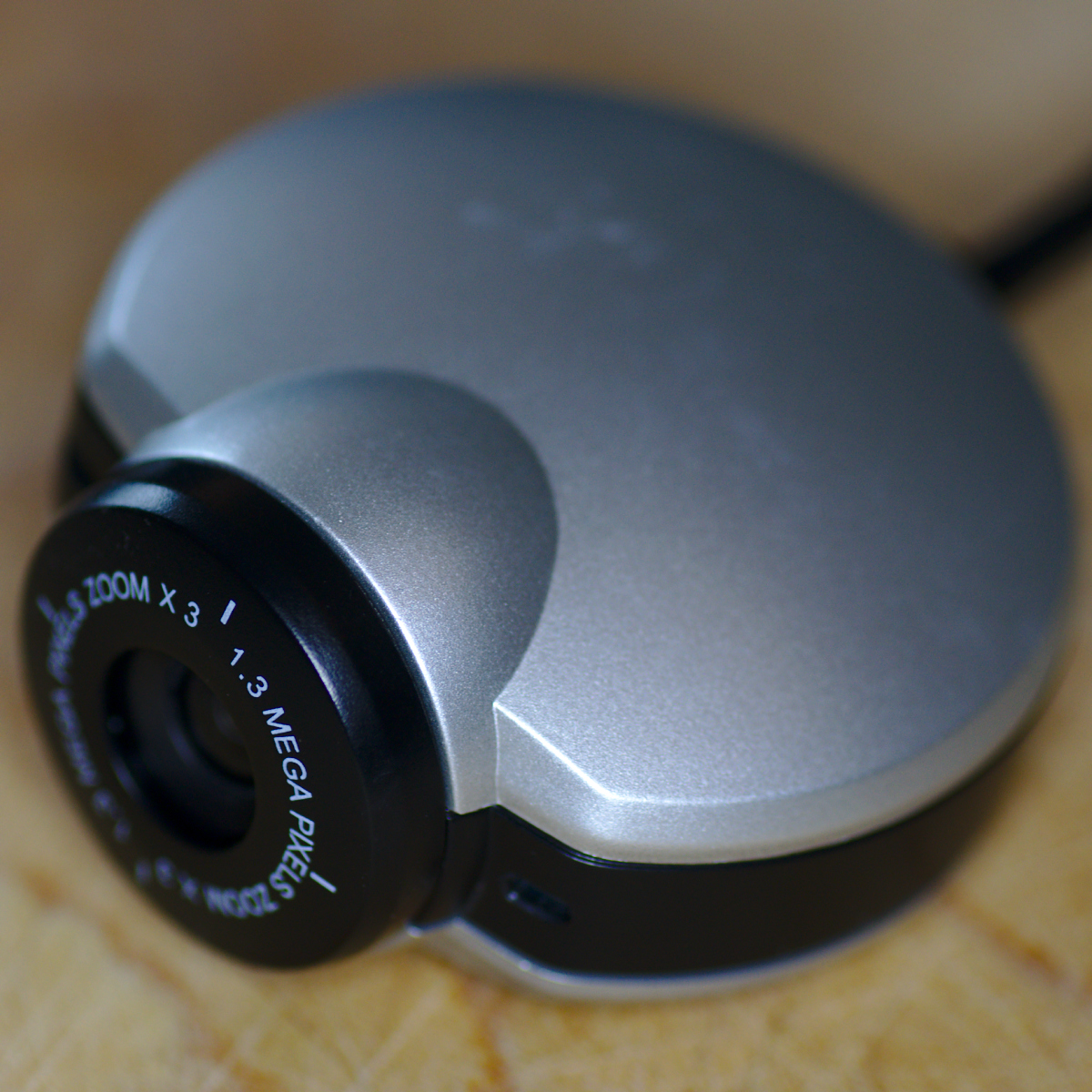
The Hercules DualPix HD webcam, to be gutted to extract the circuit board and exposed CCD imaging sensor
The powder compact was free, passed on from my wife after it was used up. The choice of case honestly isn’t important, so if you don’t have access to any powder compact, pick something else that’s interesting.

MAC powder compact, to be used as the case for the finished pinhole camera
Stripping the webcam
As well as being in a somewhat bulky case, the webcam will have a lens in front of its sensor. The whole point of a pinhole camera is that it does not use a lens, so we definitely need to remove this from the webcam. Just how this is achieved will depend entirely on the particular model of webcam used. The Hercules turned out to be very simple to disassemble – a couple of screws opened up the case, whereupon it was obvious that the lens simply screwed into a little cylinder surrounding the sensor.
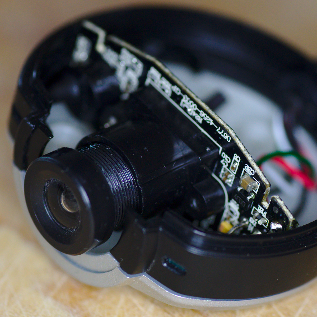
The webcam with the top part of the case removed. The case turns out to be mostly empty, with just one small circuit board to which the lens is attached. The screw thread on the lens is clearly visible and removing the lens is trivial in this case.
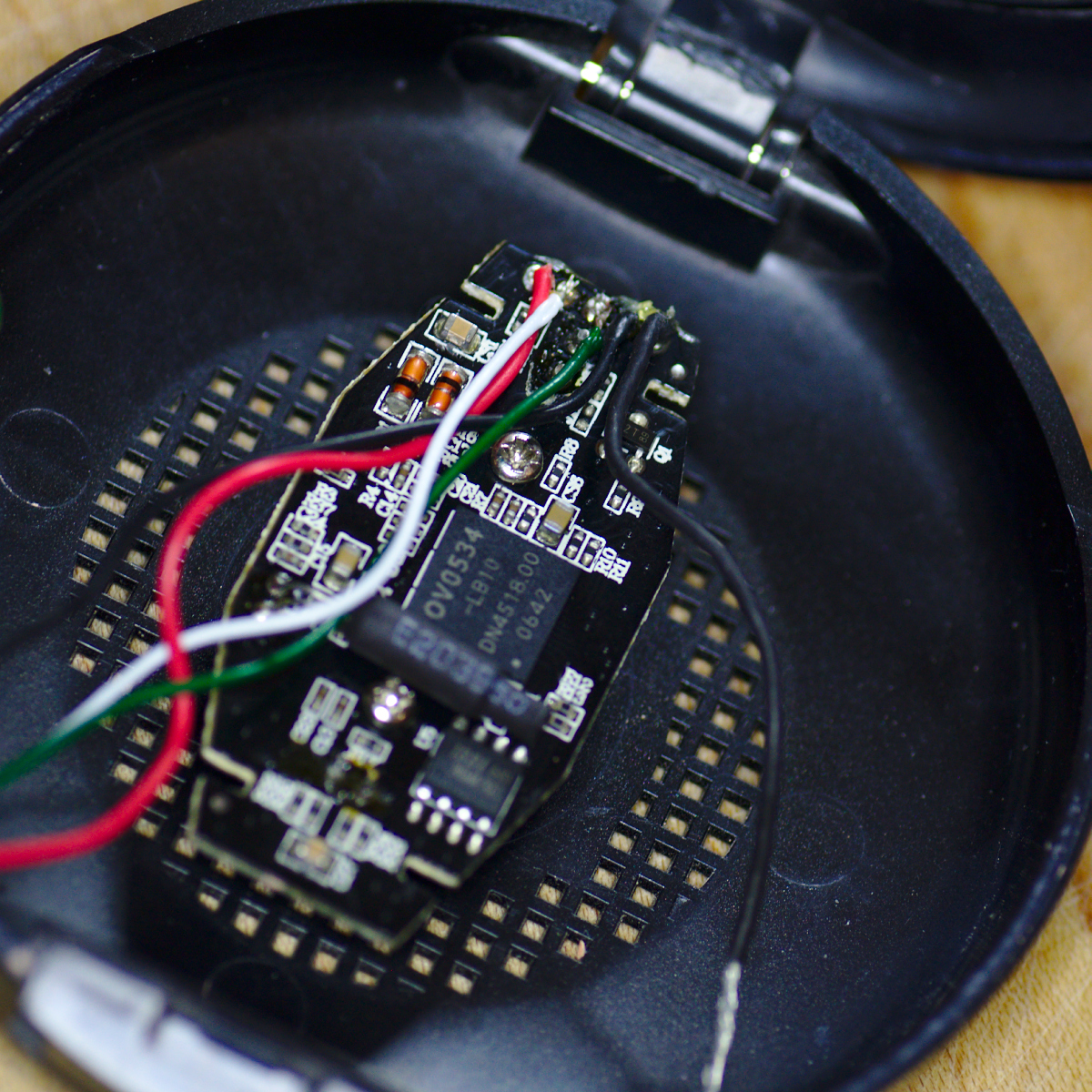
After unscrewing the lens, the bare CCD chip is exposed The lens mount protrudes quite a bit from the circuit board, and so will need trimming down to a more suitable size. It can’t be removed entirely, since it is preventing light from the adjacent power LED from spoiling the image, but it can be cut down to about 0.5cm without any trouble. The lens mount is attached to the circuit board with two small screws and easily removed, so it can be safely cut down with a scalpel with of damaging the CCD or other electronics
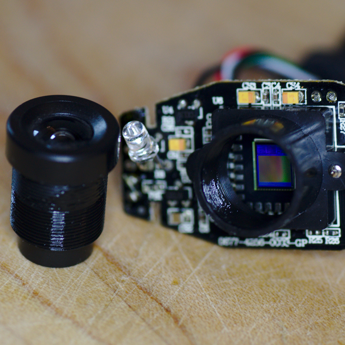
With the lens removed, the bare CCD chip is now visible. The purpose of the cylindrical collar surrounding the CCD is twofold – it both holds the lens in place and prevents light from the adjacent power LED from spoiling the image.
Not obviously visible in the pictures above, is the microphone casing which is another small cylinder of plastic protruding from the circuit board. This also needed trimming down, by simply cutting off the plastic cylinder at its base.
Connecting the webcam and Raspberry Pi
The webcam comes with a standard sized USB cable and plug attached to it, while the Raspberry Pi Zero only has a micro-USB slot. A simple USB -> micro-USB adapter can be used to connect the two together, but it gets quite bulky protruding several centimeters from the Raspberry Pi circuit board, meaning it would not comfortably fit inside the powder compact case.
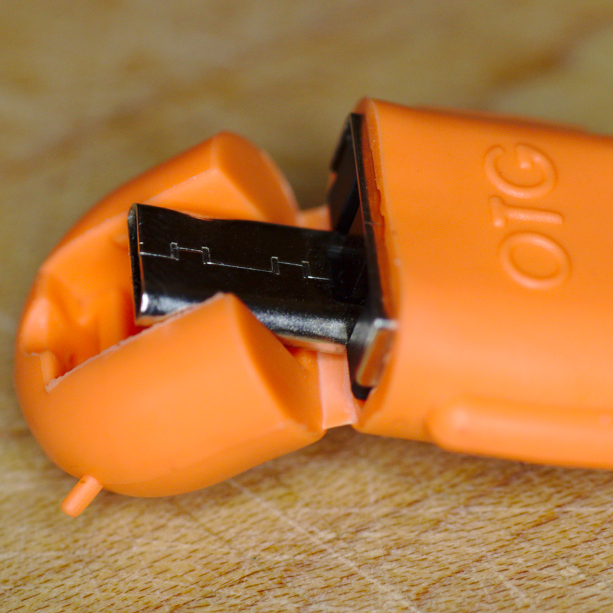
A USB to micro-USB plug adapter, shown here with its bright orange plastic casing. It will be used to connect the webcam to the Raspberry Pi Zero
The first step was to simply remove the horrifically colured orange plastic casing on the USB adapter. This made it slimmer, meaning it didn’t clash with the USB plug to power the Raspberry Pi (the two USB ports on the Raspberry Pi Zero are uncomfortably close together).
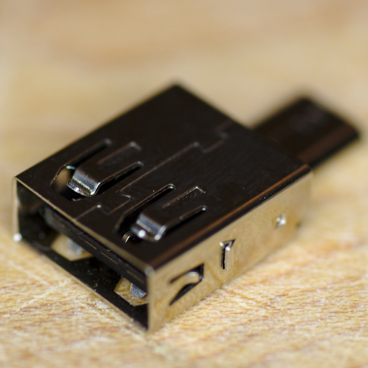
The USB to micro-USB plug adapter, stripped of its horrific orange plastic casing. This made it considerably slimmer, but did nothing for its length
Since the USB adapter barely cost £1 on eBay, I decided to try hacking into it, with the thought that it might be possible to solder the wires from the webcam’s USB cable directly onto the micro-USB plug, and do away with the bulky standard USB socket part of the adapter. As seen in the picture above, the USB socket part had a convenient seem down the middle of it, and a pair of needle nose pliers quickly broke into that. Bending the metal back & forth to promote fatigue eventually enabled it to be entirely ripped off, leaving only the micro-USB plug and the hard black plastic interior to which it was attached. A scalpel was used to cut away at the black plastic until four metal tracks were revealed. These are associated with the individual USB pins, and are more than large enough to be soldered onto.
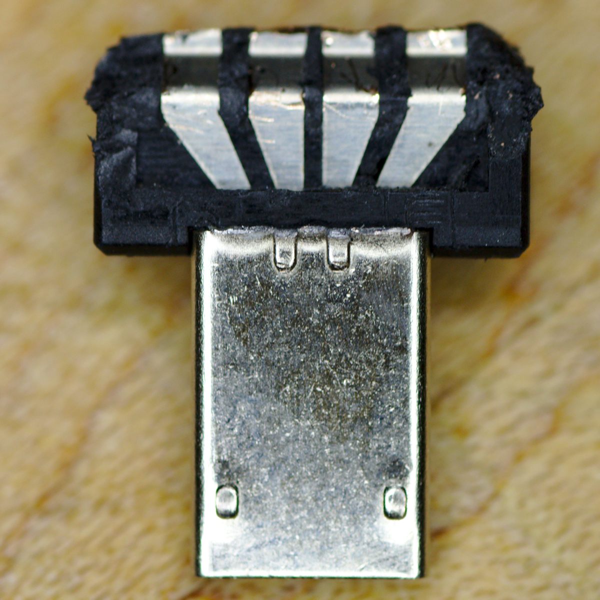
The remains of the USB to micro-USB adapter after the USB socket had been ripped off and the black plastic interior cut away to reveal the four metal tracks leading to the individual USB pins.
With micro-USB adapter suitably prepared (aka hacked to pieces), the USB cable for the webcam could be attached. The original cable was about 1 meter in length which is way too long and bulky to be concealed inside the chosen case. The Raspberry Pi would be placed directly on top of the webcam circuit board, so the cables didn’t need to be more than about 5 cm in length. Thus the webcam USB cable was trimmed right down and the outer sheaf was removed to expose the 4 individual wires inside. The wires were now soldered directly to the micro-USB plug, being sure to get the colors in the correct order 🙂
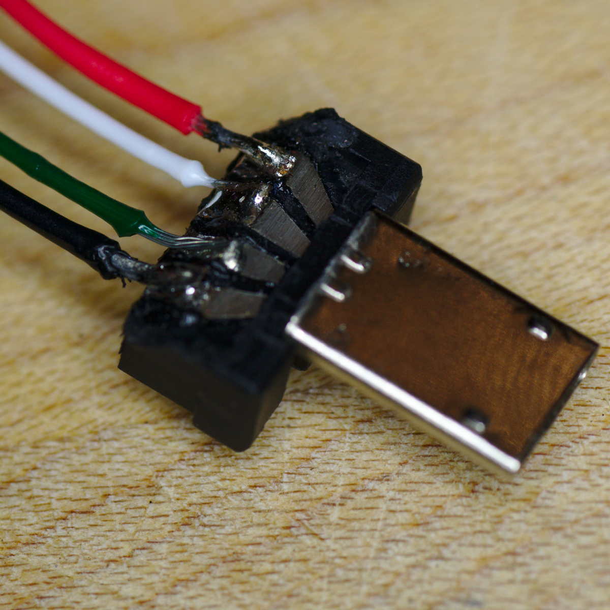
The stripped down micro-USB plug with the webcam USB cable strands directly soldered onto the individual contact strips. The plug now protrudes only about 1 cm from the Raspberry Pi Zero when attached.
Status LEDs
Although the webcam has an LED that illuminates when capturing an image, it is surface mounted on the board and won’t be visible once inside the case. The Raspberry Pi Zero has an array of GPIO (General Purpose Input Output) pins, which can be used to drive LEDs from software without much trouble. The plan is to have 2 LEDs, a yellow one that illuminates to provide overall status of the camera (ie whether it has power and has detected the camera) and a green one that illuminates whenever an image is being captured. It isn’t safe to connect the LEDs directly to the GPIO pins as they would draw too much current, so each is connected in series with a 300 Ohm resistor. There are a number of GPIO pins which could be used, and I chose to connect the positive LED wires with pins BCM 17 and BCM 18, and the negatives both to a common ground, as seen on the pinout diagram.
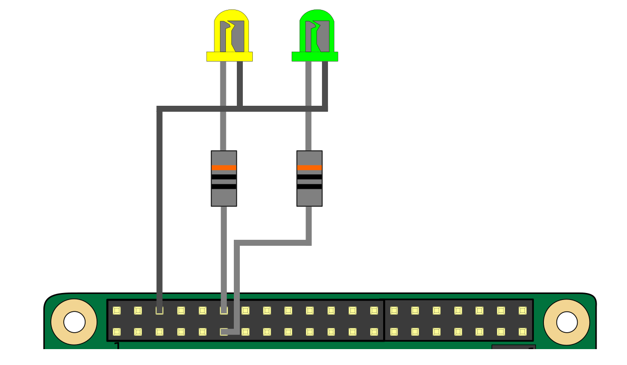
The LEDs are connected to GPIO pins BCM 17 and BCM 18, with a 300 Ohm resistor in series with each, and common ground.
The LEDs used were 3mm in size and a low power, high intensity variety. Since the plan was to have the LEDs sticking out of the powder compact lid, they were connected straight to the circuit board, instead some short lengths of wire were used.
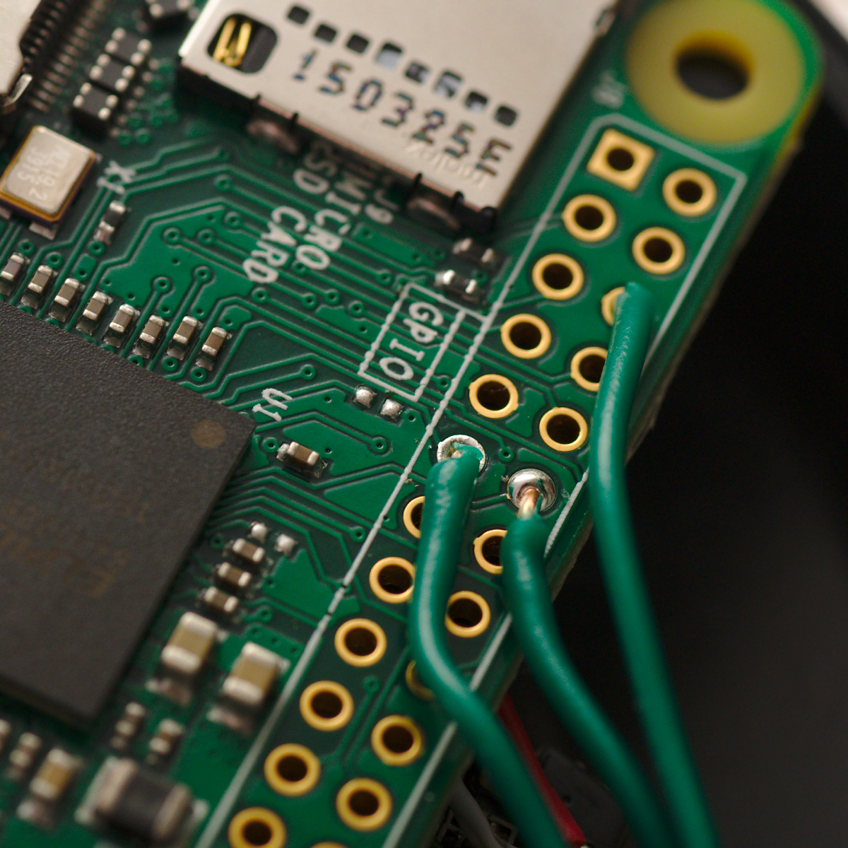
Wires soldered into the GPIO pins, leading off to the LEDs and resistors. Pins BCM 17 & BCM 18 go to the positive, while they share a common ground pin.
Preparing the powder compact
The powder compact destined for use as the case of the pinhole camera needed a little bit of simple modification. It is a basic clam-shell design, but also has an interior shelf that needs to be removed to make more space for the circuit boards.
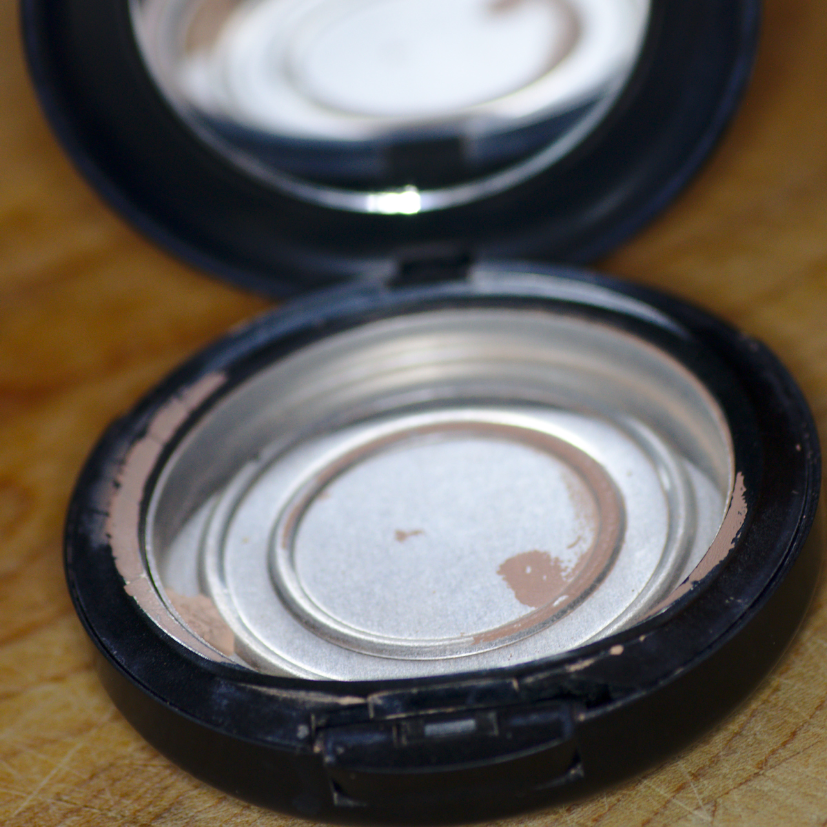
The powder compact clam-shell case showing the interior shelf that needs to be removed. Originally this tray held the powder, as can be seen from the residue.
The shelf was attached at the hinge point. One option to remove it would be to punch out the pins that form the hinge, but I didn’t have any suitable implement to do this job. Thus the handy scalpel was used once more to hack through the plastic attaching the shelf to the hinge. With this removed, there is now considerably more space inside the case. At this point two small holes need to be drilled in the lid, through which the status LEDS will poke.
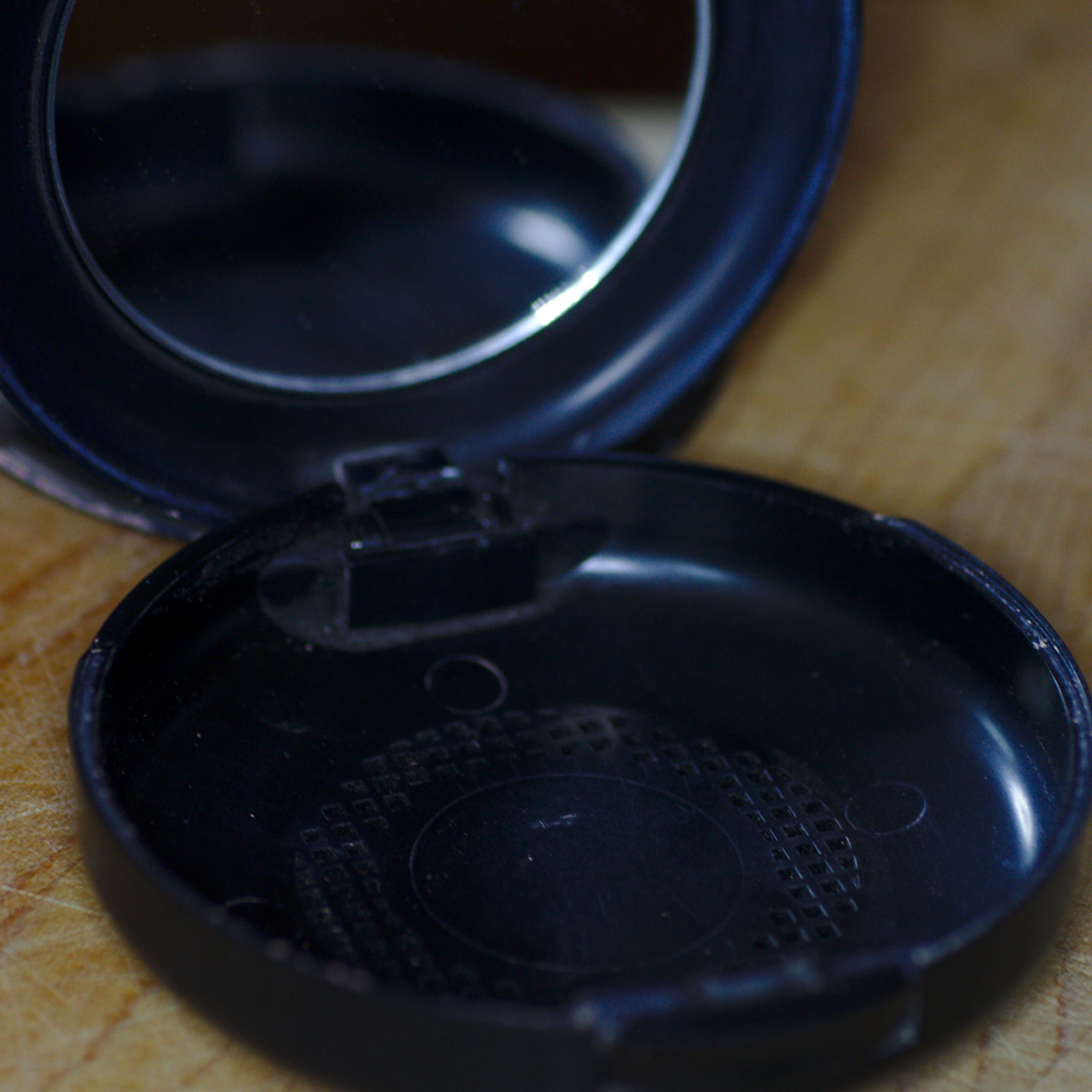
The powder compact with the tray removed. The bottom of the case has a perforated grid, while the top still holds the mirror which is not easy to remove and so left in place.
There were two further modifications that needed making to the case. The first is to make a nice round hole in the dead center of the bottom which will ultimately form the pinhole aperture. A drill with 5mm bit easily makes a suitably sized hole. A small square of kitchen tin foil is cut out (later the foil is replaced with a piece of more robust tin can) and a pinhole made in it using just the tip of the smallest sewing needle available at home. This is then glued onto the bottom of the case, so the pinhole is lined up in the center of the 5mm hole just drilled in the case.
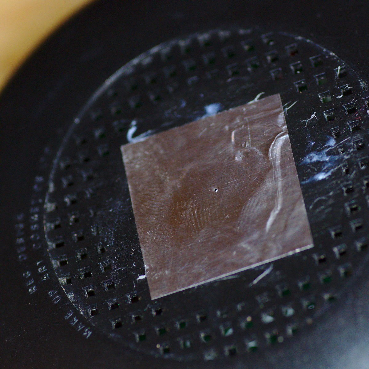
The bottom of the case showing the tin foil containing the pinhole aperture. The tin foil isn’t ideal as it is quite fragile, but it is also easy enough to replace if needed.
While the case is large enough to hold the webcam and Raspberry Pi Zero, there is still the small matter of a power source. The Pi takes power via GPIO pins or another mini-USB socket. I already had a suitably sized USB lithium ion power tank, so decided to power the Pi via the mini-USB socket. With the powder compact case closed though, there would be no way for the USB cable from the battery to get in. To address this, a scalpel was used to hack out a chunk of plastic in the side of the case, sized directly to accept the plug from the USB cable connected to the battery.
Assembling the final camera
With all the pieces prepared, the final construction task is to assemble then inside the case. The webcam board is the first to go in. It needs to be accurately positioned so that the CCD sensor is centered precisely on the pinhole in the bottom of the case. I chose to use a little bit of bluetak to hold it to the case, to make it easy to adjust the exact position as well as enabling its removal later if needed.
The webcam in place, with the CCD sensor positioned directly over the pinhole in the bottom of the case. The webcam is simply held in place with a little bluetak.
The Raspberry Pi Zero circuit board is then positioned on top of the webcam board, at 90 degrees. The underneath of the Pi circuit board was covered in electrical tape to prevent any short circuit with the webcam board beneath it. The Pi Zero is an absolutely perfect fit for the powder compact case, having barely 1mm to spare at the side, which also means it did not need anything to hold it in position. Merely closing the lid of the case applied sufficient pressure to hold it tight.
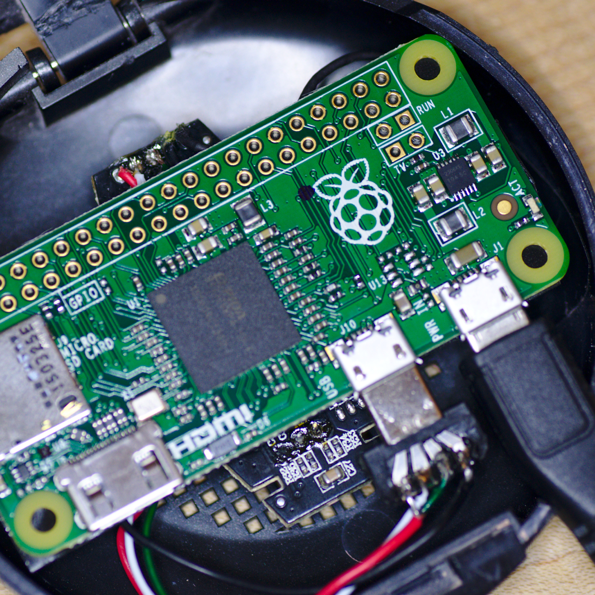
The Raspberry Pi Zero slotted into the case with barely 1mm of clearance at the edge. The hacked up micro-USB plug connected to the webcam below is alongside the micro-USB plug from the battery.
With the two circuit boards inserted, and the power cable for the battery attached, the case can be closed to reveal the finished pinhole camera. At first glance the powder compact looks just like it did before. Only the battery cable coming out of its side hints at something special going on inside.
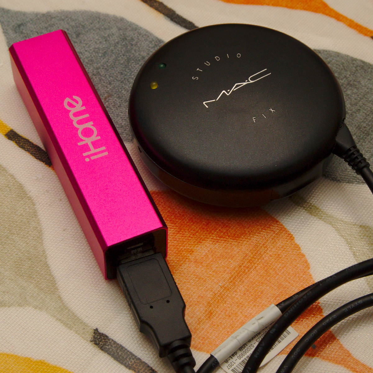
The finished camera, entirely hidden inside the powder compact case. The only hint of something unusual is the USB cable coming out of the side.
The control software
The observant readers will now be wondering how the camera is actually to be used, after all there is no keyboard, mouse or display attached to the Raspberry Pi Zero to allow it to be controlled. This lack of controls is entirely intentional. One of the most appealing aspects of pinhole photography is that it strips back the process of taking pictures to an absolute minimum. All the photographer can really do is control where the camera is positioned, the direction it points and how long the “shutter” is open. The comparison to modern digital cameras where there are many 100’s of menu options and controls is like night & day. The goal was for the digital pinhole camera to remain true to analogue pinhole cameras and keep things absolutely minimal in every sense.
Thus the decision was made to not even run a full operating system on the Raspberry Pi Zero, but instead just launch a single application. The Pi would boot the Linux kernel, mount the SD card to be used for storing captured images, and then launch a custom written application that would communicate with the webcam. The first iteration of this software simply captures 5 images in a row at the highest resolution allowed by the webcam, waiting 3 seconds between each shot. The images are saved to the SD card storage and the Pi shuts down again where upon the battery would be unplugged. To take a further 5 images is simply a matter of plugging in the battery once again. The webcam is left to decide the exposure itself, so there’s no actual shutter required for the pinhole camera – the software simply grabs a still frame every 3 seconds.
The source code for this software is published for interested readers.