Capella (α Aurigae)
Capella is a box camera made out of lego, exposing onto photographic paper
- Motivation
- Design
- Gallery
Design
The are no formal designs needed for the construction of a lego pinhole camera, it can be any shape or size that’s desired. From a practicality point of view, it would make sense to build it to a size that matched the dimensions of one of the common paper sizes (eg 4×6″). The dimensions of the camera illustrated in this page, however, were constrained by the available lego blocks, slightly off-square at 14×16 blocks. After the size, the next design consideration is how to open and close the box to allow the photographic paper to be inserted for exposures. The decision was made to construct the box as two nesting halves, with a partial overlap to prevent light leaks.
The top half of the box has a 4×4 gap in the middle which will be covered by a metal plate in which the pinhole is made. The outer wall is a single block width and three blocks high. The inner wall is also a single block width, but only two blocks high.
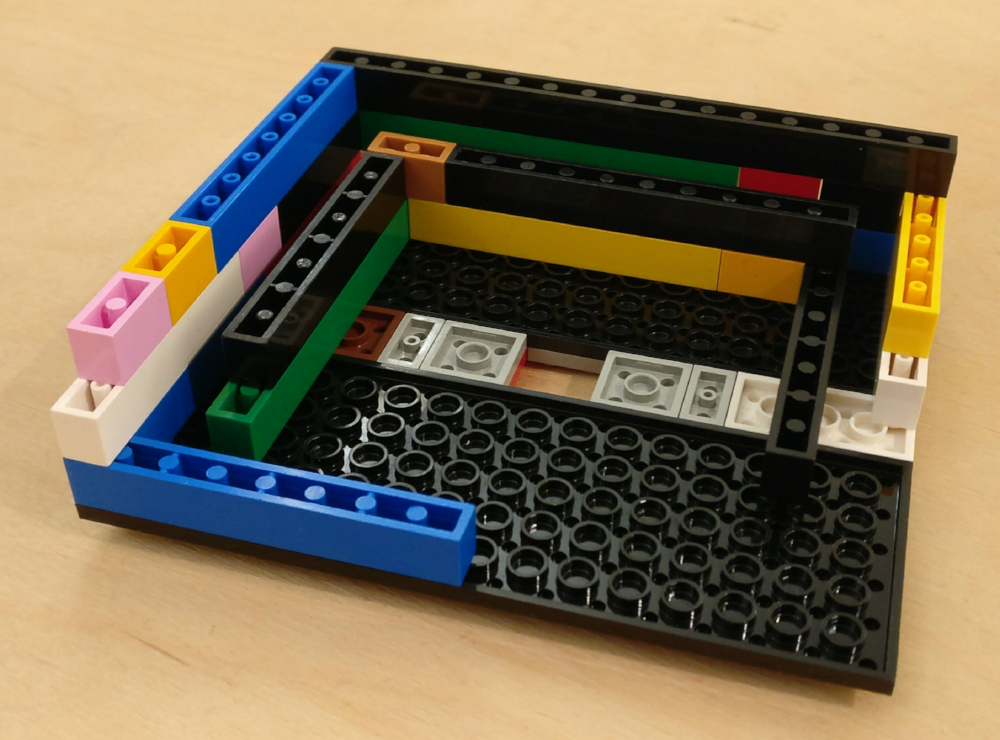
Top half of the box under construction. Note the second internal wall intended to overlap with the bottom half to ensure the join is light proof. The 2×2 hole in the middle will later be covered by the pinhole plate.
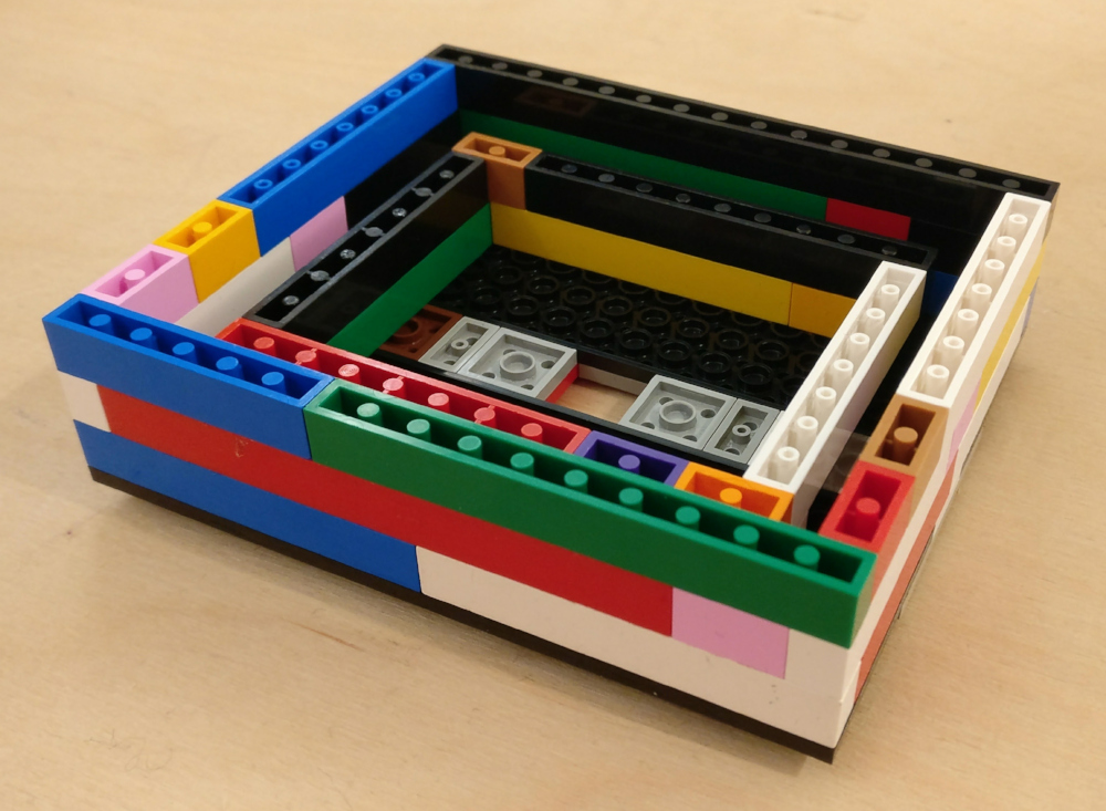
Top half of the box completed. Note the second internal wall intended to overlap with the bottom half to ensure the join is light proof. The 2×2 hole in the middle will later be covered by the pinhole plate.
The bottom half of the box has three rows which are double block width, followed by another two rows of single block width. This is topped by thin strips to add strength to the single block wall. The single block rows are positioned so they will slide between the inner and outer walls of the top half of the box.
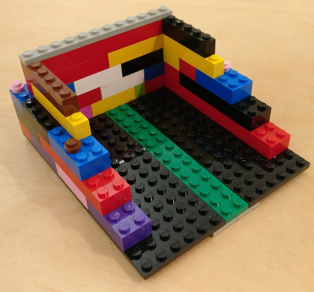
Bottom half of box under construction. Notice the top two rows are made with single width blocks to interlock with the top half to form a light proof seal.
If the top and bottom half of the box were allowed to connect along the entire length of the walls, it would be very difficult to separate the two halves again to insert/remove the photographic paper. Thus six thin single block pieces were placed around the edges of the bottom half. The top and bottom pieces are thus secured with just 6 blocks, instead of 56. This is sufficient to hold the two halves together during exposure, while allowing them to be easily separated.
Bottom half of box under construction. Notice the top two rows are made with single width blocks to interlock with the top half to form a light proof seal. The final thin top strip is to provide strength to the blocks.
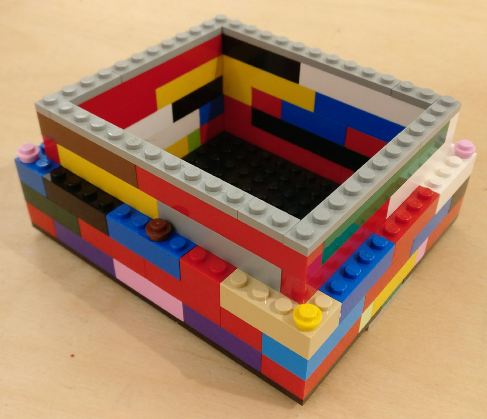
Once the two halves of the box were constructed, it was immediately apparent that lego is not at all light proof. The largest problem is that there are significant gaps between the blocks, even when tightly fitted together. To address this problem, a sheet of self-adhesive black felt was cut out to line all the interior surfaces of the box. To test light proofing, the box was held up against a bright spotlight, which revealed a few remaining leaks where an extra layer of felt was needed.
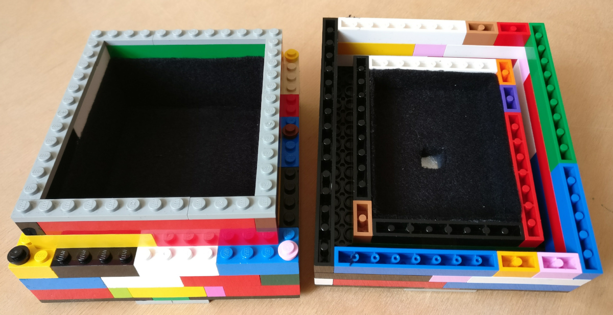
Felt lining of boxes. The blocks are not light proof on their own, so the entire interior must be lined in black felt. The bottom half has 6 single bump disks which connect with the top half. This holds the two halves together well enough for capturing images, while still allowing easy separation to remove the paper.
With the main box assembled the only remaining problem is how to provide a “shutter” control over the pinhole. The simple approach would be to just have a piece of black tape over the pinhole when not exposing an image. The complex solution involves building a mechanical shutter from some technical lego pieces. A few pieces were assembled to create a pivoting mechanism that would lift up and rotate away from the pinhole to enable an exposure to be made. It clips into the lid of the box to hold it securely in place when not exposing.
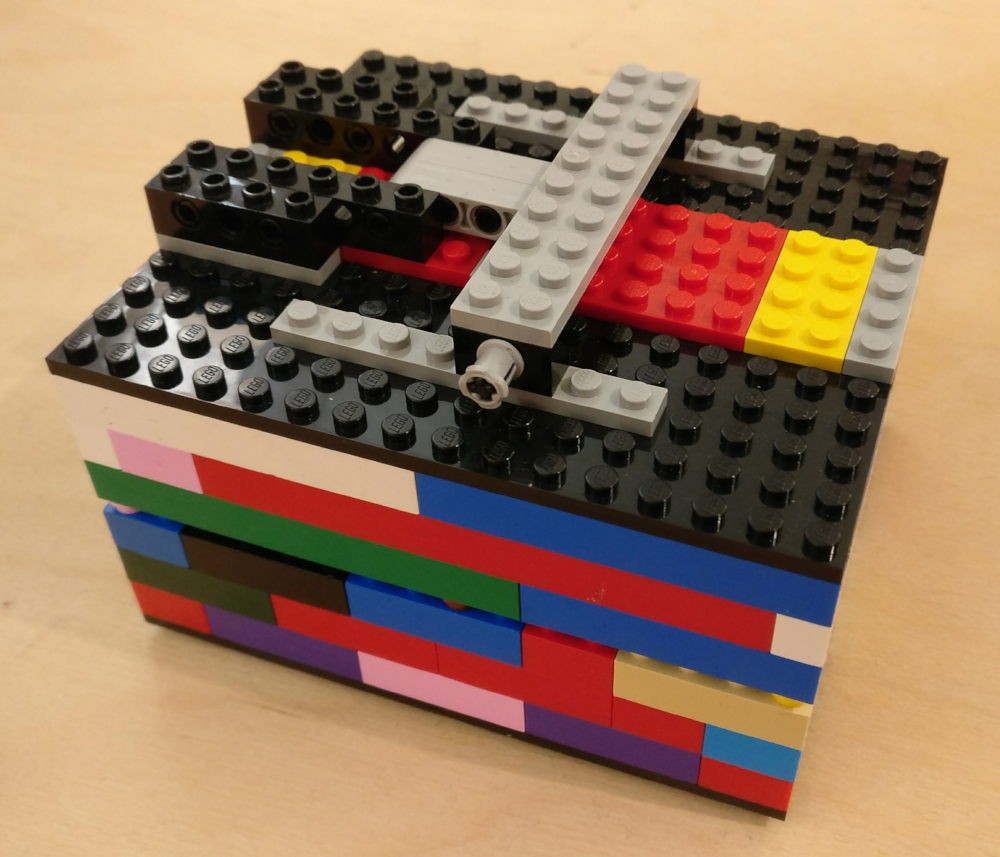
Completed camera, showing shutter mechanism in closed position. The two halves of the box are held together by 6 single bump blocks so they are secure, yet easy to separate.
In the open the position, the shutter rotates down to fully uncover the pinhole plate. The actual pinhole is made in a very thin piece of zinc/aluminum plate – a piece from a drinks can would be sufficient, but any similar thickness metal is acceptable.
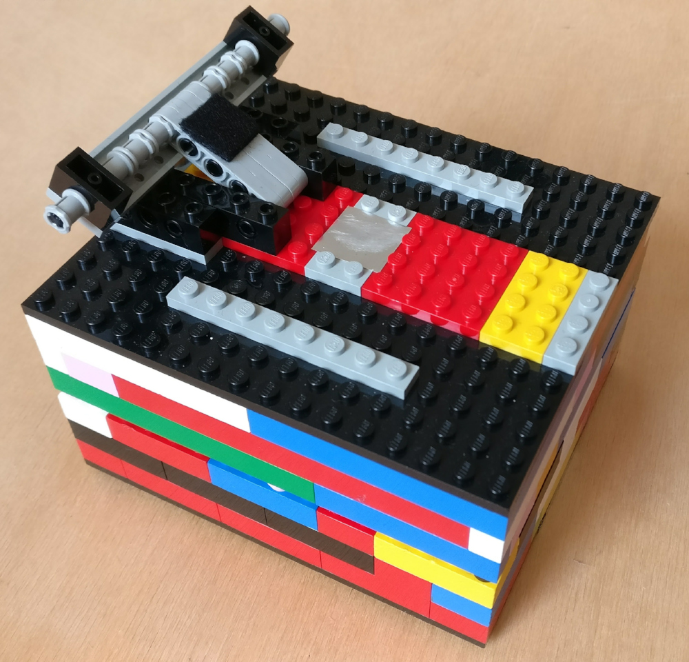
The completed camera. The shutter mechanism swings open to reveal the metal pinhole plate in the center of the box. A little black felt on the underside of the shutter ensures no light leak when in the closed position.
The pictures show the box on its back, but when in use it would be stood up on its side so the pinhole is pointing at the subject to be captured. The finished box holds photographic paper that is approximately 8x9cm in size. A fortunate side effect of lining the box in felt is that it helps to hold the paper in place during exposure. The paper used for exposures is cut out from a sheet of 8×10″, giving about 6 pieces per sheet. When using the camera, the two halves of the box need to be separated and paper inserted, either in complete darkness, or under red safe light conditions. If the camera is being used “out in the field”, the best approach is to have a changing bag and small black light proof bags to hold the paper. This would allow multiple exposures to be made before having to return to the darkroom for development. As luck would have it, the paper used in the camera is small enough that it fits conveniently into a development tank used for 1/4 size glass plates. Once the paper is in the development tank, it can be processed in day light, so a darkroom is not even required.